Introduction
One often-overlooked aspect of manufacturing equipment design is maintainability. The presence—or absence—of maintainability features can significantly affect the cost of keeping equipment operational. These costs, in turn, have a direct impact on the profitability of maintenance contracts. Therefore, finding effective ways to reduce these costs is essential to improving maintenance contract profitability.
Statistical Process Control
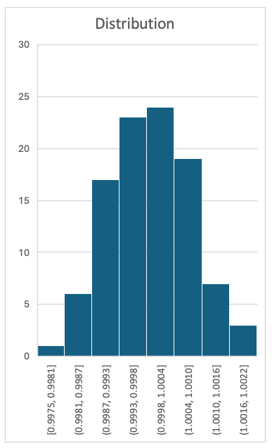
Statistical Process Control (SPC) employs established statistical methods to monitor the stability of a production process, helping to reduce waste and rework. SPC can be applied to any process that is measurable and exhibits variation that approximates a normal distribution. For example, if a process produces widgets with a target length of 1 unit and the variation follows a normal distribution, measuring 100 widgets and plotting the data in a histogram would yield a chart like the following:
SPC works by comparing actual sample measurements to expected values using a control chart. The expected values are based on the mean and standard deviation calculated from measurements collected during a baseline or training period. A control chart generally includes three key reference lines:
- Center Line (CL): The average (mean) of the training measurements.
- Upper Control Limit (UCL): The highest value considered “in control,” typically set at three standard deviations above the mean for a normally distributed process.
- Lower Control Limit (LCL): The lowest value considered “in control,” usually set at three standard deviations below the mean.
As new sample measurements are collected, they are plotted on the process control chart and evaluated against the control limits. If a sample measurement falls between the UCL and LCL, the process is considered “in control” and operating as expected. Additional rules—such as detecting trends, cycles, or multiple consecutive points near the control limits—can be applied to identify early signs of instability or emerging issues.
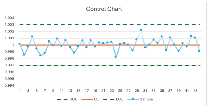
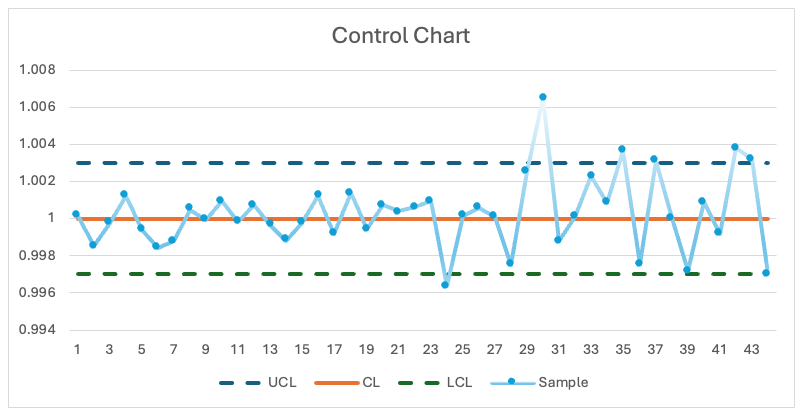
A control chart can detect shifts in both the sample mean and variability. In the example below, the sample mean decreases over time, indicating that the process is moving “out of control.”
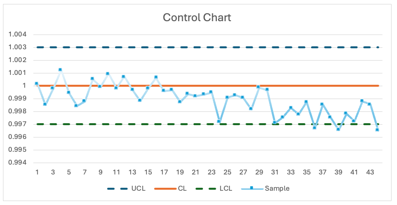
In the chart below, the sample variability increases over time, signaling that the process is becoming unstable or moving “out of control.”
Fault Detection or Predictive Maintenance?
A process that is statistically “out of control” is not the same as a process failure. Ideally, the statistical control limits should lie within the process tolerance or specification limits, so a process that is “out of control” according to the control charts may still produce outputs that meet the quality specifications. For example, consider the widget scenario above, with a mean length of 1.000, an Upper Control Limit (UCL) of 1.003, and a Lower Control Limit (LCL) of 0.997. If the design’s nominal length is 1.000 with a tolerance of ±0.005, the Upper Specification Limit (USL) would be 1.005 and the Lower Specification Limit (LSL) 0.995. This corresponds to a Process Capability Index (Cpk) of 1.67, which indicates that the process is “capable” and normally produces output within specifications.
When the process mean is centered between the specification limits, the Cpk is the ratio of the quality specification limits over the statistical control limits, quantifying how well a process can produce output within specification limits. A higher Cpk value indicates a more capable and consistent process.
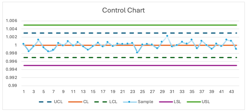
Below is a control chart with the USL and LSL lines added.
When the control limits are inside the specification limits, the control chart can serve as an effective indicator for when preventive maintenance is needed. If a process is “out of control” but still operating within specifications, it likely requires preventive maintenance but does not need to be stopped immediately.
However, if the control limits are outside the specification limits, the process is considered not capable (has a Cpk less than 1.0). In this situation, statistical control limits cannot reliably indicate when preventive maintenance is necessary before production faults occur.
Monitor the Process, not the Output
In many cases, a unit of manufacturing equipment lacks awareness of the specific products it is producing or how well it is producing them. For example, equipment making widgets may not “know” that the target length is 1.000, nor have direct knowledge of the actual lengths being produced. This raises the question: how can the equipment use SPC to monitor quality?
While the equipment may not directly measure the quality of the output, it can often monitor the processes involved in production. In other words, it can track process parameters and conditions that influence the quality of the final product.
Some examples of process attributes in semiconductor manufacturing equipment that could be monitored include:
- Light source intensity
- Image quality (e.g., focus, contrast, brightness)
- Gas flow rates
- Gas pressures in lines or chambers
- Voltages
- Currents
- Speeds (e.g. rotational or translational)
- Environmental pressures (atmospheric, vacuum)
- Temperature
- Duration (e.g. command completion time)
Actual vs. Expected
A key requirement for any process attribute used in process control is that it must be measurable through a sensor—it must be based on actual sensor data. Process control works by comparing measured values to expected values, though some pre-processing of the raw measurements is often necessary.
Consider a closed-loop gas cooling system as an example. The gas flow rate is controlled by a mass flow controller (MFC), with the setpoint determined by a process parameter. A suitable control measurement in this case would be the actual gas flow rate.
The first pre-processing step is typically to identify when the gas flow is in a steady state. Measurements taken while the gas is off, or during transient periods immediately after a setpoint change, are unlikely to be useful. The time required for the flow rate to stabilize can be determined experimentally.
If the system operates with only one flow rate setpoint, the process is straightforward: use the flow rate setpoint as the expected value and the measured flow rate as the actual value.
However, with multiple flow rate setpoints, additional pre-processing is required because SPC assumes a single mean and variability. Here are two ways to handle this:
- If there are only a few discrete setpoints, a separate control chart—with its own mean and variability—can be created for each setpoint.
- Alternatively, use the flow rate error by calculating the difference between the flow rate setpoint and the actual measured flow rate. The expected value of this flow rate error is zero. If the expected variability changes between distinct setpoints, a mapping function can be developed experimentally to adjust for these differences.
Cimetrix CIMControlFramework HealthIndicators
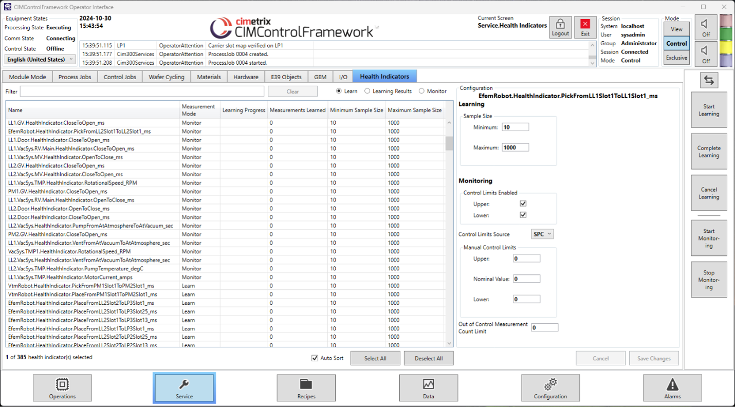
Cimetrix CIMControlFramework (CCF) is an equipment automation framework built on Microsoft .NET Framework technology. The CCF solution allows equipment manufacturers to address supervisory control, material handling, platform and process control, and factory automation requirements. By interfacing with equipment hardware and publishing data, CCF is uniquely positioned to effectively monitor equipment performance. The CCF HealthIndicators feature integrates Statistical Process Control (SPC) with powerful, intuitive GUI-based management tools to provide comprehensive monitoring of the equipment. Leveraging CCF HealthIndicators can help reduce maintenance costs by enabling proactive maintenance and early detection of potential issues.
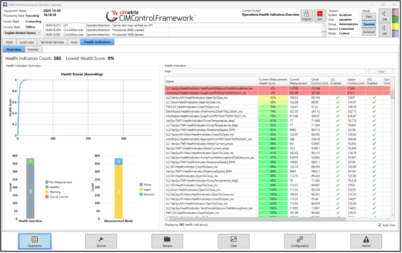
The CCF screen used to teach and configure health indicators.
The CCF screen with a summary view of all health indicators.